|
|
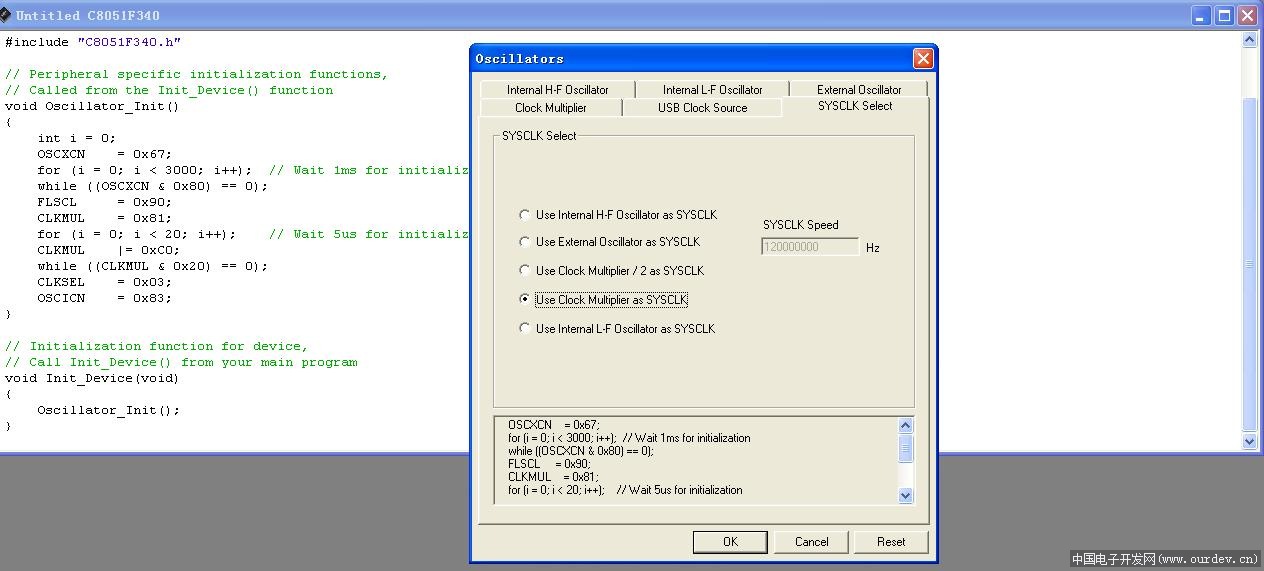
24MHz外部晶振进去后用时钟乘法器倍到96MHz
明天做一下高低温试验,如成功再汇报.
//-----------------------------------------------------------------------------
// F34x_PCA0_Software_Timer_Blinky.c
//-----------------------------------------------------------------------------
// In this example, PCA Module 0 is used to generate the interrupt, and the
// port pin driving the LED is configured for push-pull mode.
//
// Pinout:
//
// P2.2 - LED (push-pull)
//
// all other port pins unused
//
//-----------------------------------------------------------------------------
// Includes
//-----------------------------------------------------------------------------
#include <C8051F340.h> // SFR declarations
//-----------------------------------------------------------------------------
// Global Constants
//-----------------------------------------------------------------------------
#define SYSCLK 96000000 // Internal oscillator frequency in Hz
#define LED_FREQUENCY 100000 // Frequency to blink LED at in Hz
#define T0_CLOCKS 240 // Use 120 clocks per T0 Overflow
// SYSCLK cycles per interrupt
#define PCA_TIMEOUT ((SYSCLK/T0_CLOCKS)/LED_FREQUENCY/2)
sfr16 PCA0CP0 = 0xFB; // PCA0 Compare Register Definition
sbit LED = P2^2; // LED='1' means ON
//-----------------------------------------------------------------------------
// Function Prototypes
//-----------------------------------------------------------------------------
void Oscillator_Init (void);
void Port_Init (void);
void PCA0_Init (void);
//-----------------------------------------------------------------------------
// Global Variables
//-----------------------------------------------------------------------------
unsigned int NEXT_COMPARE_VALUE; // Next edge to be sent out in HSO mode
//-----------------------------------------------------------------------------
// main() Routine
//-----------------------------------------------------------------------------
void main (void) {
// Disable watchdog timer
PCA0MD = 0x00;
Port_Init (); // Initialize crossbar and GPIO
Oscillator_Init (); // Initialize oscillator
PCA0_Init (); // Initialize PCA0
EA = 1; // Globally enable interrupts
while (1); // Spin here to wait for ISR
}
//-----------------------------------------------------------------------------
// Initialization Subroutines
//-----------------------------------------------------------------------------
//-----------------------------------------------------------------------------
// Oscillator_Init
void Oscillator_Init (void)
{
//OSCICN = 0x83; // Set internal oscillator to run
// at its maximum frequency
//CLKSEL = 0x00; // Select the internal osc. as
// the SYSCLK source
int i = 0;
OSCXCN = 0x20;
FLSCL = 0x90;
CLKMUL = 0x81;
for (i = 0; i < 20; i++); // Wait 5us for initialization
CLKMUL |= 0xC0;
while ((CLKMUL & 0x20) == 0);
CLKSEL = 0x23;
OSCICN = 0x03;
}
//-----------------------------------------------------------------------------
// Port_Init
//-----------------------------------------------------------------------------
//
// Return Value : None
// Parameters : None
//
// This function configures the crossbar and GPIO ports.
//
// No crossbar peripherals are used for this example.
//
// P2.2 is set to Push-Pull mode.
//
//-----------------------------------------------------------------------------
void Port_Init (void)
{
// XBR0 = 0x00;
//XBR1 = 0x40; // No peripherals routed to pins
// Enable crossbar and weak pull-ups
//P2MDOUT |= 0x04; // Set LED (P2.2) to push-pull
// P0.0 - Unassigned, Open-Drain, Digital
// P0.1 - Unassigned, Open-Drain, Digital
// P0.2 - Unassigned, Open-Drain, Digital
// P0.3 - Unassigned, Open-Drain, Digital
// P0.4 - Unassigned, Open-Drain, Digital
// P0.5 - Unassigned, Open-Drain, Digital
// P0.6 - Unassigned, Open-Drain, Digital
// P0.7 - Skipped, Open-Drain, Digital
// P1.0 - Unassigned, Open-Drain, Digital
// P1.1 - Unassigned, Open-Drain, Digital
// P1.2 - Unassigned, Open-Drain, Digital
// P1.3 - Unassigned, Open-Drain, Digital
// P1.4 - Unassigned, Open-Drain, Digital
// P1.5 - Unassigned, Open-Drain, Digital
// P1.6 - Unassigned, Open-Drain, Digital
// P1.7 - Unassigned, Open-Drain, Digital
// P2.0 - Unassigned, Open-Drain, Digital
// P2.1 - Unassigned, Open-Drain, Digital
// P2.2 - Unassigned, Push-Pull, Digital
// P2.3 - Unassigned, Open-Drain, Digital
// P2.4 - Unassigned, Open-Drain, Digital
// P2.5 - Unassigned, Open-Drain, Digital
// P2.6 - Unassigned, Open-Drain, Digital
// P2.7 - Unassigned, Open-Drain, Digital
// P3.0 - Unassigned, Open-Drain, Digital
// P3.1 - Unassigned, Open-Drain, Digital
// P3.2 - Unassigned, Open-Drain, Digital
// P3.3 - Unassigned, Open-Drain, Digital
// P3.4 - Unassigned, Open-Drain, Digital
// P3.5 - Unassigned, Open-Drain, Digital
// P3.6 - Unassigned, Open-Drain, Digital
// P3.7 - Unassigned, Open-Drain, Digital
P2MDOUT = 0x04;
P0SKIP = 0x80;
XBR1 = 0x40;
}
//-----------------------------------------------------------------------------
// PCA0_Init
//-----------------------------------------------------------------------------
//
// Return Value : None
// Parameters : None
//
// This function configures the PCA time base to use T0 Overflows as a clock
// source. Timer0 is also configured by this routine for 8-bit auto-reload
// mode, where T0_CLOCKS is the number of System clocks per T0 Overflow.
// The code then sets up Software Timer mode for Module 0 (CEX0 pin).
//
// On every interrupt from Module 0, software toggles the port I/O pin for the
// LED. The frequency of the LED toggling is determined by the parameter
// CEX0_FREQUENCY.
//
// Using different PCA clock sources, different T0 reload values, or a
// different processor clock will result in a different frequency for the LED
// square wave, and different maximum and minimum options.
//
// -------------------------------------------------------------------------
// How "Software Timer Mode" Works:
//
// The PCA's Software Timer Mode works by generating an interrupt for the
// associated module every time the PCA0 register increments and the new
// 16-bit PCA0 counter value matches the module's capture/compare
// register (PCA0CPn).
//
// By loading the PCA0CPn register with the next match value every time a
// match happens, arbitrarily timed interrupts can be generated.
// -------------------------------------------------------------------------
//
// When setting the capture/compare register for the next match value, the low
// byte of the PCA0CPn register (PCA0CPLn) should be written first, followed
// by the high byte (PCA0CPHn). Writing the low byte clears the ECOMn bit,
// and writing the high byte will restore it. This ensures that a match does
// not occur until the full 16-bit value has been written to the compare
// register. Writing the high byte first will result in the ECOMn bit being
// set to '0' after the 16-bit write, and the next match will not occur at
// the correct time.
//
// It is best to update the capture/compare register as soon after a match
// occurs as possible so that the PCA counter will not have incremented past
// the next desired edge value. This code implements the compare register
// update in the PCA ISR upon a match interrupt.
//
//-----------------------------------------------------------------------------
void PCA0_Init (void)
{
// Configure Timer 0 for 8-bit auto-reload mode, using SYSCLK as time base
TMOD &= 0xF0; // Clear all T0 control bits
TMOD |= 0x02; // 8-bit auto-reload timer
CKCON |= 0x04; // T0 uses SYSCLK
TH0 = -T0_CLOCKS; // Set up reload value
TL0 = -T0_CLOCKS; // Set up initial value
// Configure PCA time base; overflow interrupt disabled
PCA0CN = 0x00; // Stop counter; clear all flags
PCA0MD = 0x04; // Use Timer 0 as time base
PCA0CPM0 = 0x49; // Module 0 = Software Timer Mode,
// Enable Module 0 Interrupt flag,
// Enable ECOM bit
PCA0L = 0x00; // Reset PCA Counter Value to 0x0000
PCA0H = 0x00;
PCA0CPL0 = PCA_TIMEOUT & 0x00FF; // Set up first match
PCA0CPH0 = (PCA_TIMEOUT & 0xFF00) >> 8;
// Set up the variable for the following match
NEXT_COMPARE_VALUE = PCA0CP0 + PCA_TIMEOUT;
EIE1 |= 0x10; // Enable PCA interrupts
CR = 1; // Start PCA
TR0 = 1; // Start Timer 0
}
//-----------------------------------------------------------------------------
// Interrupt Service Routines
//-----------------------------------------------------------------------------
//-----------------------------------------------------------------------------
// PCA0_ISR
//-----------------------------------------------------------------------------
//
// Return Value : None
// Parameters : None
//
// This is the ISR for the PCA. It handles the case when a match occurs on
// channel 0, and updates the PCA0CPn compare register with the value held in
// the global variable "NEXT_COMPARE_VALUE".
//
//-----------------------------------------------------------------------------
void PCA0_ISR (void) interrupt 11
{
if (CCF0) // If Module 0 caused the interrupt
{
CCF0 = 0; // Clear module 0 interrupt flag.
PCA0CPL0 = (NEXT_COMPARE_VALUE & 0x00FF);
PCA0CPH0 = (NEXT_COMPARE_VALUE & 0xFF00)>>8;
LED = ~LED; // Invert the LED pin
// Set up the variable for the following edge
NEXT_COMPARE_VALUE = PCA0CP0 + PCA_TIMEOUT;
}
else // Interrupt was caused by other bits.
{
PCA0CN &= ~0x86; // Clear other interrupt flags for PCA
}
}
//-----------------------------------------------------------------------------
// End Of File
//----------------------------------------------------------------------------- |
阿莫论坛20周年了!感谢大家的支持与爱护!!
曾经有一段真挚的爱情摆在我的面前,我没有珍惜,现在想起来,还好我没有珍惜……
|


 发表于 2012-3-7 17:16:57
 楼主
楼主

 年人这也能超!