搜索
bottom↓
回复: 0

一个verilog写的状态机在不同条件下的仿真波形产生的原因探究

[复制链接]

出0入0汤圆

发表于 2011-7-16 09:30:46 | 显示全部楼层 |阅读模式
这是在ISE12.4上编译,链接到modelsim se6.5仿真的模块代码和测试代码。

//StateMachine.v    version 1  状态机模块
module StateMachine(Clock, Reset, A, K2, K1, state);
       
        input Clock, Reset, A;
        output K2, K1;
        output[1:0] state;
       
        reg K2, K1;
        reg[1:0] state;
       
        parameter Idle                = 2'b 00,
                                 Start        = 2'b 01,
                                 Stop                = 2'b 10,
                                 Clear        = 2'b 11;

        always @(posedge Clock)
                if(!Reset)
                        begin
                                state        <= Idle;
                                K2                <= 0;
                                K1                <= 0;
                        end
                else
                        case(state)
                                Idle:
                                        if(A)
                                                begin
                                                        state        <= Start;
                                                        K1                <= 0;
                                                end
                                        else
                                                begin
                                                        state        <= Idle;
                                                        K2                <= 0;
                                                        K1                <= 0;
                                                end
                                Start:
                                        if(!A)        state        <= Stop;
                                        else                state        <= Start;
                                Stop:
                                        if(A)
                                                begin
                                                        state        <= Clear;
                                                        K2                <= 1;
                                                end
                                        else
                                                begin
                                                        state        <= Stop;
                                                        K2                <= 0;
                                                        K1                <= 0;
                                                end
                                Clear:
                                        if(!A)
                                                begin
                                                        state        <= Idle;
                                                        K2        <= 0;
                                                        K1        <= 0;
                                                end
                                        else
                                                begin
                                                        state        <= Clear;
                                                        K2                <= 0;
                                                        K1                <= 1;
                                                end
                                default:        state        <= 2'b xx;
                        endcase
endmodule


//StateMachineTest.v测试代码

`timescale 1ns / 1ps

////////////////////////////////////////////////////////////////////////////////
// Company:
// Engineer:
//
// Create Date:   10:02:04 07/15/2011
// Design Name:  z StateMachine
// Module Name:   E:/FPGA Projects/ISE Projects/StateMachine/StateMachineTest.v
// Project Name:  StateMachine
// Target Device:  
// Tool versions:  
// Description:
//
// Verilog Test Fixture created by ISE for module: StateMachine
//
// Dependencies:
//
// Revision:*
// Revision 0.01 - File Created
// Additional Comments:
//
////////////////////////////////////////////////////////////////////////////////

module StateMachineTest;

        // Inputs
        reg Clock;
        reg Reset;
        reg A;

        // Outputs
        wire K2;
        wire K1;
        wire [1:0] state;

        // Instantiate the Unit Under Test (UUT)
        StateMachine uut (
                .Clock(Clock),
                .Reset(Reset),
                .A(A),
                .K2(K2),
                .K1(K1),
                .state(state)
        );

        initial
        begin
                // Initialize Inputs
                Clock = 0;
                // Wait 100 ns for global reset to finish
                forever #5 Clock        = ~Clock;//产生驱动时钟
                // Add stimulus here
        end
       
        initial
        begin
                A = 0;
                forever #4        A        = ~A;
        end
       
        initial
        begin
                Reset = 0;
                #50
                Reset        = 1;
        end
      
endmodule


从波形上看,每一个状态所持续的时间是相等的。

//StateMachine.v version 2 只是把case语句中的条件全部变成if(!A),而version1 的条件是一个if(A)下来一个if(!A)间隔出现。 同样的测试代码
module StateMachine(Clock, Reset, A, K2, K1, state);
       
        input Clock, Reset, A;
        output K2, K1;
        output[1:0] state;
       
        reg K2, K1;
        reg[1:0] state;
       
        parameter Idle                = 2'b 00,
                                 Start        = 2'b 01,
                                 Stop                = 2'b 10,
                                 Clear        = 2'b 11;

        always @(posedge Clock)
                if(!Reset)
                        begin
                                state        <= Idle;
                                K2                <= 0;
                                K1                <= 0;
                        end
                else
                        case(state)
                                Idle:
                                        if(!A)
                                                begin
                                                        state        <= Start;
                                                        K1                <= 0;
                                                end
                                        else
                                                begin
                                                        state        <= Idle;
                                                        K2                <= 0;
                                                        K1                <= 0;
                                                end
                                Start:
                                        if(!A)        state        <= Stop;
                                        else                state        <= Start;
                                Stop:
                                        if(!A)
                                                begin
                                                        state        <= Clear;
                                                        K2                <= 1;
                                                end
                                        else
                                                begin
                                                        state        <= Stop;
                                                        K2                <= 0;
                                                        K1                <= 0;
                                                end
                                Clear:
                                        if(!A)
                                                begin
                                                        state        <= Idle;
                                                        K2        <= 0;
                                                        K1        <= 0;
                                                end
                                        else
                                                begin
                                                        state        <= Clear;
                                                        K2                <= 0;
                                                        K1                <= 1;
                                                end
                                default:        state        <= 2'b xx;
                        endcase
endmodule
version 1的测试代码的的仿真波形如下

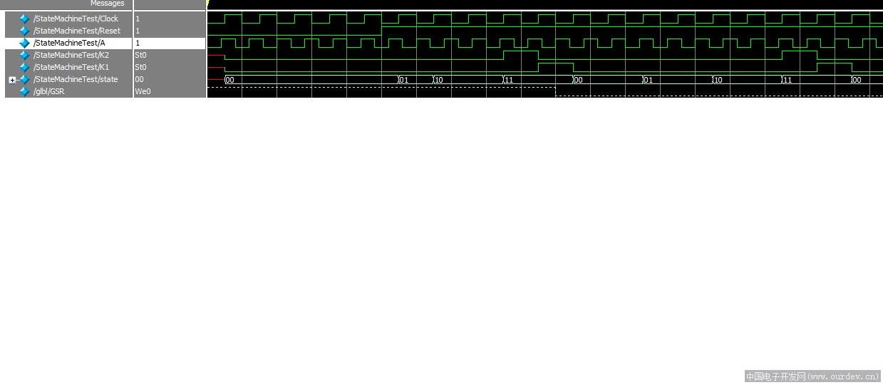
version 1 仿真波形 (原文件名:StateMachineTestWaveV1.png)

version 2 仿真波形如下

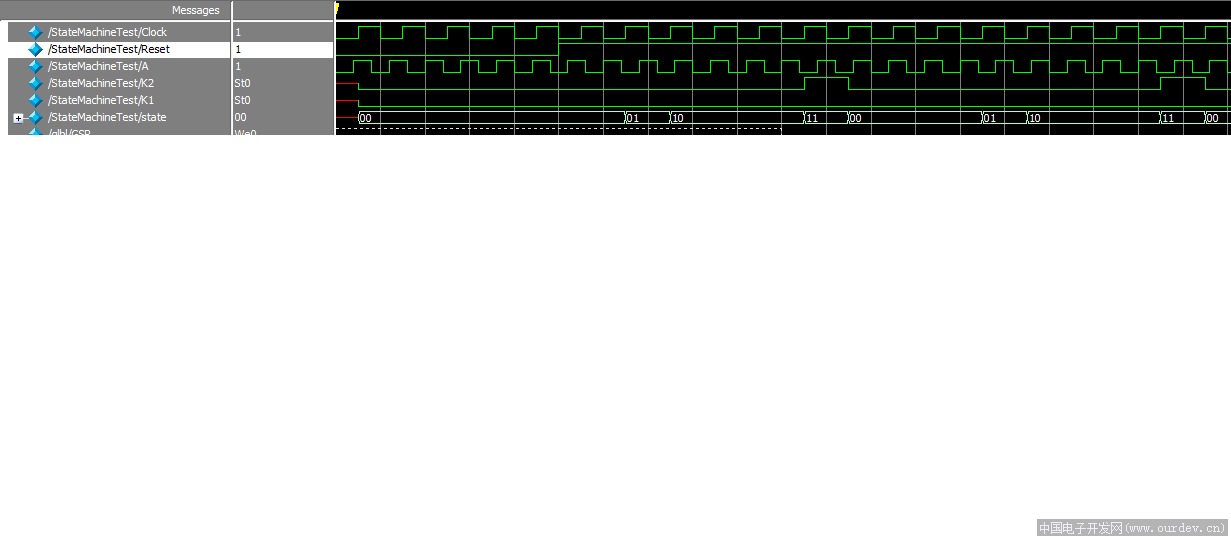
version 2 仿真波形 (原文件名:StateMachineTestWaveV2.png)


产生这种仿真波形的原因是什么呢,这两种状态跳变条件的写法有什么不同,会对它的下一级产生追求者以影响 。

阿莫论坛20周年了!感谢大家的支持与爱护!!

知道什么是神吗?其实神本来也是人,只不过神做了人做不到的事情 所以才成了神。 (头文字D, 杜汶泽)
回帖提示: 反政府言论将被立即封锁ID 在按“提交”前,请自问一下:我这样表达会给举报吗,会给自己惹麻烦吗? 另外:尽量不要使用Mark、顶等没有意义的回复。不得大量使用大字体和彩色字。【本论坛不允许直接上传手机拍摄图片,浪费大家下载带宽和论坛服务器空间,请压缩后(图片小于1兆)才上传。压缩方法可以在微信里面发给自己(不要勾选“原图),然后下载,就能得到压缩后的图片。注意:要连续压缩2次才能满足要求!!】。另外,手机版只能上传图片,要上传附件需要切换到电脑版(不需要使用电脑,手机上切换到电脑版就行,页面底部)。
您需要登录后才可以回帖 登录 | 注册

本版积分规则

手机版|Archiver|amobbs.com 阿莫电子技术论坛 ( 粤ICP备2022115958号, 版权所有:东莞阿莫电子贸易商行 创办于2004年 (公安交互式论坛备案:44190002001997 ) )

GMT+8, 2024-7-24 13:26

© Since 2004 www.amobbs.com, 原www.ourdev.cn, 原www.ouravr.com

快速回复 返回顶部 返回列表