|
|
 发表于 2008-12-15 17:00:28
|
显示全部楼层
发表于 2008-12-15 17:00:28
|
显示全部楼层
to taoist
虽然没有原理图,不过从segger上搜到的一些资料可能对你有些帮助。
首先是segger论坛上官方回答用户的一个提问,提到V6和V7的硬件区别: Hello adikm,
the main difference between J-Link hardware version 6 and 7 is,
that in J-Link V6 the SWV support is implemented in software
and in J-Link V7 an additional pin to the UART of the target
hardware is used for the SWV support.
This is why J-Link V7 supports higher speeds in SWV mode.
Best regards, Alex
由此看出改动应该不大,多从目标板接出一个pin用于读数据而已,而且是UART端口
新的SWD/SWV接线图是这样(多了13pin的SWO的信号,这个信号是单向的):
Pin Signal Type Description
1 VTref Input This is the target reference voltage. It is used to check if the target has power, to create the logic-level reference for the input comparators and to control the output logic levels to the target. It is normally fed from Vdd of the target board and must not have a series resistor.
2 Vsupply NC This pin is not connected in J-Link. It is reserved for compatibility with other equipment. Connect to Vdd or leave open in target system.
3 Not used NC This pin is not used by J-Link. If the device may also be accessed via JTAG, this pin may be connected to nTRST, otherwise leave open.
5 Not used NC This pin is not used by J-Link. If the device may also be accessed via JTAG, this pin may be connected to TDI, otherwise leave open.
7 SWDIO I/O Single bi-directional data pin.
9 SWCLK Output Clock signal to target CPU. It is recommended that this pin is pulled to a defined state of the target board. Typically connected to TCK of target CPU.
11 Not used NC This pin is not used by J-Link. This pin is not used by J-Link when operating in SWD mode. If the device may also be accessed via JTAG, this pin may be connected to RTCK, otherwise leave open.
13 SWO Output Serial Wire Output trace port. (Optional, not required for SWD communication.)
15 RESET I/O Target CPU reset signal. Typically connected to the RESET pin of the target CPU, which is typically called "nRST", "nRESET" or "RESET".
17 Not used NC This pin is not connected in J-Link.
19 5V-Supply Output This pin is used to supply power to some eval boards. Not all JLinks supply power on this pin, only the KS (Kickstart) versions. Typically left open on target hardware.
再来看看segger对SWV这部分的描述:
Serial Wire Output (SWO) overview
J-Link can be used with devices that supports Serial Wire Output (SWO). Serial Wire Output (SWO) support means support for a single pin output signal from the core. It is currently tested with Cortex-M3 only.
Serial Wire Viewer (SWV) overview
The Instrumentation Trace Macrocell (ITM) and Serial Wire Output (SWO) can be used to form a Serial Wire Viewer (SWV). The Serial Wire Viewer provides a low cost method of obtaining information from inside the MCU. The SWO can output trace data in two output formats, but only one output mechanism is valid at any one time. The 2 defined encodings are UART and Manchester. The current J-Link implementation sup- ports only UART encoding. Serial Wire Viewer uses the SWO pin to transmit different packets for different types of information. The three sources in the Cortex-M3 core which can output information via this pin are:
Instrumentation Trace Macrocell (ITM) for application-driven trace source that supports printf-style debugging. It supports 32 different channels, which allow it to be used for other purposes such as real-time kernel information as well.
Data Watchpoint and Trace (DWT) for real-time variable monitoring and PC-sampling, which can in turn be used to periodically output the PC or various CPU-internal counters, which can be used to obtain profiling information from the target.
Timestamping. Timestamps are emitted relative to packets.
------
由此可以大胆的猜测一下,V7的SWD接口多了SWO信号用于SWV的支持。 这个信号是目标板UART接出来的,而且是单向的。从Segger的描述V7只支持SWO的uart模式,那么最方便的方法就是把这个信号接到7s64的RXD上了,具体接哪个可以试一下。 |
|


 楼主
楼主 <font color=green>(原文件名:jlink.jpg) 修改一下,等v7原理图。<font color=#699bcd>本贴被 bozai
  <font color=green>(原文件名:6.jpg)
  <font color=green>(原文件名:4.jpg)
  <font color=green>(原文件名:1.JPG)
  <font color=green>(原文件名:未命名.jpg)
 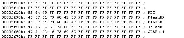 <font color=green>(原文件名:11.JPG) 其中0000FF00行是"SN"此处暂写0XFF