|
|
[2410]在U-BOOT中使用I2C命令,驱动VGA芯片CH7004/CH7005
起因:由于以前学习ARM7 s3c44b0 时使用的bootloader为u-boot,很好用,所以最近在s3c2410平台上也编译了支持nand启动的u-boot,版本为1.2.0。使用中发现有一个问题,通过vivi可以正常引导并驱动VGA的linux2.4内核文件,使用u-boot引导后,VGA驱动运行不正确,效果如下:
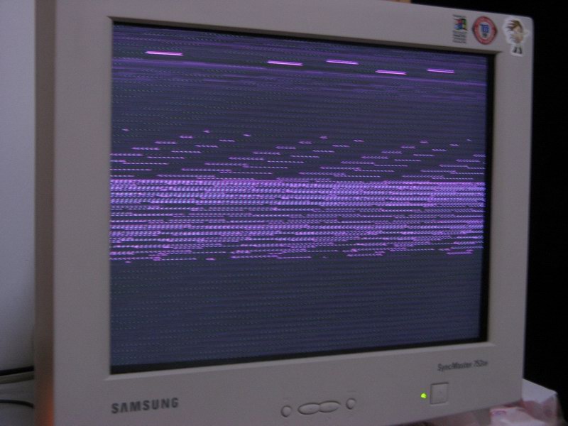
(原文件名:1.JPG)
查看vivi的启动代码,发现阳初2410板是将vga的驱动交由vivi完成,linux内核负责驱动lcd即可。该板使用的vga芯片为CH7004,网上也有板子使用的芯片为CH7005,我用过CH7013,应该都差不多,通过I2C协议,赋值芯片里的几个寄存器实现VGA输出。
CH7004需要I2C总线向地址4,7,14,13分别顺序写入0x20,0x8c,0x1b,0x03,CH7004芯片的地址为0xEC(这儿有点问题,后面会提到)。
既然vivi可以使用i2c,为何u-boot不可以,在网上搜了半天也只搜到了一篇外国blog写的如何操作u-boot里的i2c命令,算了,看文档自己来吧。
准备:我是直接对u-boot-1.2.0的样板smdk2410进行的修改
操作过程:
1、 修改include/configs/smdk2410.h 文件
1)去掉CFG_CMD_I2C | \ 的注释
2)在中间某处添加如下内容
/*-----------------------------------------------------------------------
* I2C
*----------------------------------------------------------------------*/
#define CONFIG_DRIVER_S3C24X0_I2C 1
#define CONFIG_HARD_I2C 1 /* I2C with hardware support */
//#define CONFIG_I2C_CMD_TREE 1
#undef CONFIG_SOFT_I2C /* I2C bit-banged */
#define CFG_I2C_SPEED 100000 /* I2C speed and slave address */
#define CFG_I2C_SLAVE 0x0
看似很简单,我试了一个晚上,哇哇哇,讲解下:
本来以为只要CFG_CMD_I2C 就行的,结果make错误,提示命令未定义 ,之后开始看u-boot的README(写的很好),发现要定义CONFIG_HARD_I2C 或者CONFIG_SOFT_I2C,2410是硬件支持I2C的,当然是定义硬件,能简单不少。
CFG_I2C_SPEED 是定义传输速度,不用多说,CFG_I2C_SLAVE 也必须定义,目前我还没搞清楚,是从机地址还是其他?我开始填的是CH7004的0xEC地址,后来填了0x0,结果都能用。
CONFIG_I2C_CMD_TREE 如果定义这个,可以把所有指令统一归为i2c xxxxx,但是定义了有一些错误,因为2410不能动态修改i2c的传输速度,需要在common/cmd_i2c.c注释掉相关项才行,还是不定义吧。
最关键的是CONFIG_DRIVER_S3C24X0_I2C 这个啦,搞了我一个晚上才发现要定义这个选项,cmd_i2c.c里包含了i2c.h文件,这个文件在include目录里面,是一个通用文件,但我找了好久才找到i2c.c文件,在cpu/arm920t/s3c24x0目录里面!仔细看一看,需要定义这个CONFIG_DRIVER_S3C24X0_I2C 才行!我说怎么一直make提示未定义的函数呢~~~~~~ToT
编译过后,将u-boot.bin下载到nand flash的最前面,希望能用吧。
介绍几个主要命令
iprobe 检测所有在总线上的i2c设备号(相当好用的命令)
imw i2c内存赋值,使用方法 imw 从机地址 数据地址 数据
eg. imw 0x76 4 0x20
imd 观察i2c内存
imm 自动增加地址赋值
首先用iprobe观察是否能找到i2c设备,我的返回如下:Valid chip addresses: 50 76
很奇怪,CH7004的地址竟然是76!刚开始我还以为i2c工作不正常,后来加了块24c256在板子上,出来一个新地址50,i2c工作是正常的,为什么CH7004的地址是76呢?求解
然后依次执行
imw 76 4 20
imw 76 7 8c
imw 76 14 1b
imw 76 13 3
CRT竟然毫无反应,囧,又在这困了半天,还是以为没正常工作。最后想到下载linux的uImage镜像,执行看看,竟然出来啦,开心!
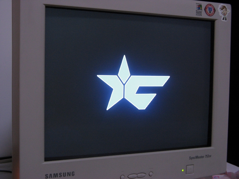
(原文件名:2.JPG)
尾声:开机启动自动初始化VGA
很简单,可以利用env来搞定
setenv vga imw 76 4 20\; imw 76 7 8c\; imw 76 14 1b\;imw 76 13 3
setenv bootcmd run vga
saveenv
注意斜杠不能漏掉,下面是我的env,我搞繁琐了,在bootcmd中还可以添加linux内核启动
bootargs=noinitrd root=/dev/mtdblock/2 console=ttySA0,115200
bootdelay=3
baudrate=115200
ethaddr=08:00:3e:26:0a:5b
ipaddr=192.168.0.54
serverip=192.168.0.1
netmask=255.255.255.0
vga1=imw 76 4 20
vga2=imw 76 7 8c
vga3=imw 76 14 1b
vga4=imw 76 13 3
vga=run vga1;run vga2;run vga3;run vga4
bootcmd=run vga
stdin=serial
stdout=serial
stderr=serial
以上,花了一天时间研究,收获颇丰!
By 阿虚
2008-8-12 22:00
附录1:U-BOOT的README中关于I2C的部分
配置
CFG_CMD_I2C * I2C serial bus support
- I2C Support: CONFIG_HARD_I2C | CONFIG_SOFT_I2C
These enable I2C serial bus commands. Defining either of
(but not both of) CONFIG_HARD_I2C or CONFIG_SOFT_I2C will
include the appropriate I2C driver for the selected cpu.
This will allow you to use i2c commands at the u-boot
command line (as long as you set CFG_CMD_I2C in
CONFIG_COMMANDS) and communicate with i2c based realtime
clock chips. See common/cmd_i2c.c for a description of the
command line interface.
CONFIG_HARD_I2C selects the CPM hardware driver for I2C.
CONFIG_SOFT_I2C configures u-boot to use a software (aka
bit-banging) driver instead of CPM or similar hardware
support for I2C.
There are several other quantities that must also be
defined when you define CONFIG_HARD_I2C or CONFIG_SOFT_I2C.
In both cases you will need to define CFG_I2C_SPEED
to be the frequency (in Hz) at which you wish your i2c bus
to run and CFG_I2C_SLAVE to be the address of this node (ie
the cpu's i2c node address).
Now, the u-boot i2c code for the mpc8xx (cpu/mpc8xx/i2c.c)
sets the cpu up as a master node and so its address should
therefore be cleared to 0 (See, eg, MPC823e User's Manual
p.16-473). So, set CFG_I2C_SLAVE to 0.
That's all that's required for CONFIG_HARD_I2C.
If you use the software i2c interface (CONFIG_SOFT_I2C)
then the following macros need to be defined (examples are
from include/configs/lwmon.h):
I2C_INIT
(Optional). Any commands necessary to enable the I2C
controller or configure ports.
eg: #define I2C_INIT (immr->im_cpm.cp_pbdir |= PB_SCL)
I2C_PORT
(Only for MPC8260 CPU). The I/O port to use (the code
assumes both bits are on the same port). Valid values
are 0..3 for ports A..D.
I2C_ACTIVE
The code necessary to make the I2C data line active
(driven). If the data line is open collector, this
define can be null.
eg: #define I2C_ACTIVE (immr->im_cpm.cp_pbdir |= PB_SDA)
I2C_TRISTATE
The code necessary to make the I2C data line tri-stated
(inactive). If the data line is open collector, this
define can be null.
eg: #define I2C_TRISTATE (immr->im_cpm.cp_pbdir &= ~PB_SDA)
I2C_READ
Code that returns TRUE if the I2C data line is high,
FALSE if it is low.
eg: #define I2C_READ ((immr->im_cpm.cp_pbdat & PB_SDA) != 0)
I2C_SDA(bit)
If <bit> is TRUE, sets the I2C data line high. If it
is FALSE, it clears it (low).
eg: #define I2C_SDA(bit) \
if(bit) immr->im_cpm.cp_pbdat |= PB_SDA; \
else immr->im_cpm.cp_pbdat &= ~PB_SDA
I2C_SCL(bit)
If <bit> is TRUE, sets the I2C clock line high. If it
is FALSE, it clears it (low).
eg: #define I2C_SCL(bit) \
if(bit) immr->im_cpm.cp_pbdat |= PB_SCL; \
else immr->im_cpm.cp_pbdat &= ~PB_SCL
I2C_DELAY
This delay is invoked four times per clock cycle so this
controls the rate of data transfer. The data rate thus
is 1 / (I2C_DELAY * 4). Often defined to be something
like:
#define I2C_DELAY udelay(2)
CFG_I2C_INIT_BOARD
When a board is reset during an i2c bus transfer
chips might think that the current transfer is still
in progress. On some boards it is possible to access
the i2c SCLK line directly, either by using the
processor pin as a GPIO or by having a second pin
connected to the bus. If this option is defined a
custom i2c_init_board() routine in boards/xxx/board.c
is run early in the boot sequence.
CONFIG_I2CFAST (PPC405GP|PPC405EP only)
This option enables configuration of bi_iic_fast[] flags
in u-boot bd_info structure based on u-boot environment
variable "i2cfast". (see also i2cfast)
命令
imd - i2c memory display
imm - i2c memory modify (auto-incrementing)
inm - i2c memory modify (constant address)
imw - i2c memory write (fill)
icrc32 - i2c checksum calculation
iprobe - probe to discover valid I2C chip addresses
iloop - infinite loop on address range
附录2: 外国介绍u-boot 上i2c操作的文章,可惜地址忘了
I2C Configuration to use the GPIO on the u-boot
For using the GPIO writes the value 0xef to the address 0x00 of a chip at address 0x38 on the u-boot prompt.
=> setenv lcd "imw 0x38 0x00 0xef"
=> printenv lcd
lcd=imw 0x38 0x00 0xef
If it is always enabled at the boot, then add `run lcd' script in your boot parameter and save settings to the flash memory.
=> printenv nfshdboot
nfshdboot=run lanphyinit;tftp 1000000 mpc8349e/uImage;run nfshdboot_args addtty addmisc; bootm 1000000
=> setenv nfshdboot "run lcd; run lanphyinit;tftp 1000000 mpc8349e/uImage;run nfshdboot_args addtty addmisc; bootm 1000000"
=> saveenv
Saving Environment to Flash...
Un-Protected 2 sectors
Erasing Flash... done
Erased 2 sectors
Writing to Flash... done KB
Protected 2 sectors
=> run nfshdboot
另外一篇
I2C operation on the u-boot
I2C operation for PCF8574A and DS1339
=> iexp
Reading I2C expander PCF8574(A) (U8, U10)
PCF8574A (U8) chip: 0x38 data: 255
LED0 and LED1 are flashing.
Hit any key to exit ...
VSC8201_PWN: 1
MPCI_PME#: 1
LCD_EN: 1
PCF8574A (U10) chip: 0x39 data: 250
Board Revision: 10
CF-CD#: 1 (CompactFlash absent)
MPCI_CLKRUN#: 1
PCI_M66EN: 1 (66 MHz PCI)
BOOT0#: 1 (U7)
=> imd 38 0.0 1 (i2c address) (address).(byte size) (num of byte)
0000: ff .
=> imd 39 0.0 1
0000: fa .
=> imd 68 0 7
0000: 21 36 12 04 31 91 b5 !6..1..
12:36:21 b5/91/31(04)
b0 second
b1 minute
b2 hour
b3 days
b4 day
b5 month
b6 year
01 Sun
02 Mon
03 Tue
04 Wed
05 Thu
06 Fri
07 Sat
Please refer MPC8349E-mITXE_schematic.pdf on page.4 for the details of pin assaign of these ICs.
U8 PCF8574A (0x38) (default value: 1111,1111)
b0 led0 0/1 on/off
b1 led1 0/1 on/off
b2 vsc8201_pwn
b3 mpci_pme#
b4 lcd_en 0/1 en/dis
b5 n.c.
b6 n.c.
b7 n.c.
U10 PCF8574A (0x39) (default value: 1111,1010)
b0 rev1
b1 rev0
b2 reserved
b3 cf-cd#
b4 mpci_clkrun#
b5 pci_m66en
b6 boot0#
b7 n.c.
U62 DS1339U-33 (0x68)
Enable the LCD
lcd_en=1: 1110,1111 0xEF
=> imm 38 0
(interactive i2c memory modify)
0000: ef .
00001: (if stop modifing, Cntrl + C) |
阿莫论坛20周年了!感谢大家的支持与爱护!!
曾经有一段真挚的爱情摆在我的面前,我没有珍惜,现在想起来,还好我没有珍惜……
|


 发表于 2008-8-12 22:02:15