|
|
 发表于 2008-8-10 15:19:29
|
显示全部楼层
发表于 2008-8-10 15:19:29
|
显示全部楼层
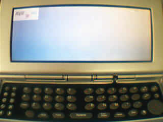
shdzbsl:屏应该还没有问题的。
你试试我的测试代码。现在显示好像正常了一些。
主要改了 REG0x02屏的位数(原来这里指接口位数),应该是四位,也就是0x04
其它设置为16位色的。
希望大家多交流
void LCM_TEST(void)
{
volatile unsigned char * pRegs = REGISTER_OFFSET;
volatile unsigned char * pMem;
volatile unsigned char * pLUT;
volatile unsigned char * pTmp;
volatile unsigned char * pCursor;
long lpCnt;
int idx;
int rgb;
long x, y;
/*
** Initialize the chip.
*/
DDRC = 0xff;
PORTC = 0x00;
XMCRB |= (1<<XMM0);// 禁用A15 ///////////////////////
LCM_CS_ON();
LCM_REG();
/*
** Step 1: Enable the host interface.
**
** Register 1B: Miscellaneous Disable - host interface enabled, half frame
** buffer enabled.
*/
*(pRegs + 0x1B) = 0x00; /* 0000 0000 */
/*
** Step 2: Disable the FIFO
*/
*(pRegs + 0x23) = 0x80; /* 1000 0000 */
/*
** Step 3: Set Memory Configuration
**
** Register 1: Memory Configuration - 4 ms refresh, EDO
*/
*(pRegs + 0x01) = 0x30; /* 0011 0000 */
/*
** Step 4: Set Performance Enhancement 0 register
*/
*(pRegs + 0x22) = 0x24; /* 0010 0100 */
/*
** Step 5: Set the rest of the registers in order.
*/
/*
** Register 2: Panel Type - 16-bit, format 1, color, dual, passive.
*/
*(pRegs + 0x02) = 0x04; /* 0010 0100 */
/*
** Register 3: Mod Rate
*/
*(pRegs + 0x03) = 0x00; /* 0000 0000 */
/*
** Register 4: Horizontal Display Width (HDP) - 640 pixels
** (640 / 8) - 1 = 79t = 4Fh
*/
*(pRegs + 0x04) = 0x4f; /* 0100 1111 */
/*
** Register 5: Horizontal Non-Display Period (HNDP)
** PCLK
** Frame Rate = -----------------------------
** (HDP + HNDP) * (VDP + VNDP)
**
** 16,500,000
** = -----------------------------
** (640 + HNDP) * (480 + VNDP)
**
** HNDP and VNDP must be calculated such that the desired frame rate
** is achieved.
*/
*(pRegs + 0x05) = 0x0B; /* 0001 1111 */
/*
** Register 6: HRTC/FPLINE Start Position - applicable to CRT/TFT only.
*/
*(pRegs + 0x06) = 0x00; /* 0000 0000 */
/*
** Register 7: HRTC/FPLINE Pulse Width - applicable to CRT/TFT only.
*/
*(pRegs + 0x07) = 0x00; /* 0000 0000 */
/*
** Registers 8-9: Vertical Display Height (VDP) - 480 lines.
** 480/2 - 1 = 239t = 0xEF
*/
*(pRegs + 0x08) = 0xEF; /* 1110 1111 */
*(pRegs + 0x09) = 0x00; /* 0000 0000 */
/*
** Register A: Vertical Non-Display Period (VNDP)
** This register must be programed with register 5 (HNDP)
** to arrive at the frame rate closest to the desired
** frame rate.
*/
*(pRegs + 0x0A) = 0x1D; /* 0000 0001 */
/*
** Register B: VRTC/FPFRAME Start Position - applicable to CRT/TFT only.
*/
*(pRegs + 0x0B) = 0x00; /* 0000 0000 */
/*
** Register C: VRTC/FPFRAME Pulse Width - applicable to CRT/TFT only.
*/
*(pRegs + 0x0C) = 0x00; /* 0000 0000 */
/*
** Register D: Display Mode - 8 BPP, LCD disabled.
*/
*(pRegs + 0x0D) = 0x14; //0x14 /* 0000 1100 */
/*
** Registers E-F: Screen 1 Line Compare - unless setting up for
** split screen operation use 0x3FF.
*/
*(pRegs + 0x0E) = 0xFF; /* 1111 1111 */
*(pRegs + 0x0F) = 0x03; /* 0000 0011 */
/*
** Registers 10-12: Screen 1 Display Start Address - start at the
** first byte in display memory.
*/
*(pRegs + 0x10) = 0x00; /* 0000 0000 */
*(pRegs + 0x11) = 0x00; /* 0000 0000 */
*(pRegs + 0x12) = 0x00; /* 0000 0000 */
/*
** Register 13-15: Screen 2 Display Start Address - not applicable
** unless setting up for split screen operation.
*/
*(pRegs + 0x13) = 0x00; /* 0000 0000 */
*(pRegs + 0x14) = 0x00; /* 0000 0000 */
*(pRegs + 0x15) = 0x00; //0x00 /* 0000 0000 */
/*
** Register 16-17: Memory Address Offset - this address represents the
** starting WORD. At 8BPP our 640 pixel width is 320
** WORDS
*/
*(pRegs + 0x16) = 0x80; //0x80 /* 0100 0000 */
*(pRegs + 0x17) = 0x02; //0x02 /* 0000 0001 */
/*
** Register 18: Pixel Panning
*/
*(pRegs + 0x18) = 0x00; /* 0000 0000 */
/*
** Register 19: Clock Configuration - In this case we must divide
** PCLK by 2 to arrive at the best frequency to set
** our desired panel frame rate.
*/
*(pRegs + 0x19) = 0x01; //0x02 /* 0000 0001 */
/*
** Register 1A: Power Save Configuration - enable LCD power, CBR refresh,
** not suspended.
*/
*(pRegs + 0x1A) = 0x00; /* 0000 0000 */
/*
** Register 1C-1D: MD Configuration Readback - these registers are
** read only, but it's OK to write a 0 to keep
** the register configuration logic simpler.
*/
*(pRegs + 0x1C) = 0x00; /* 0000 0000 */
*(pRegs + 0x1D) = 0x00; /* 0000 0000 */
/*
** Register 1E-1F: General I/O Pins Configuration
*/
*(pRegs + 0x1E) = 0x00; /* 0000 0000 */
*(pRegs + 0x1F) = 0x00; /* 0000 0000 */
/*
** Register 20-21: General I/O Pins Control
*/
*(pRegs + 0x20) = 0x00; /* 0000 0000 */
*(pRegs + 0x21) = 0x00; /* 0000 0000 */
/*
** Registers 24-26: LUT control.
** For this example do a typical 8 BPP LUT setup.
**
** Setup the pointer to the LUT data and reset the LUT index register.
** Then, loop writing each of the RGB LUT data elements.
*/
pLUT = LUT8;
*(pRegs + 0x24) = 0;
for (idx = 0; idx < 256; idx++)
{
for (rgb = 0; rgb < 3; rgb++)
{
*(pRegs + 0x26) = *pLUT;
pLUT++;
}
}
/*
** Register 27: Ink/Cursor Control - disable ink/cursor
*/
*(pRegs + 0x27) = 0x00; /* 0000 0000 */
/*
** Registers 28-29: Cursor X Position
*/
*(pRegs + 0x28) = 0x00; /* 0000 0000 */
*(pRegs + 0x29) = 0x00; /* 0000 0000 */
/*
** Registers 2A-2B: Cursor Y Position
*/
*(pRegs + 0x2A) = 0x00; /* 0000 0000 */
*(pRegs + 0x2B) = 0x00; /* 0000 0000 */
/*
** Registers 2C-2D: Ink/Cursor Color 0 - blue
*/
*(pRegs + 0x2C) = 0x1F; /* 0001 1111 */
*(pRegs + 0x2D) = 0x00; /* 0000 0000 */
/*
** Registers 2E-2F: Ink/Cursor Color 1 - green
*/
*(pRegs + 0x2E) = 0xE0; /* 1110 0000 */
*(pRegs + 0x2F) = 0x07; /* 0000 0111 */
/*
** Register 30: Ink/Cursor Start Address Select
*/
*(pRegs + 0x30) = 0x00; /* 0000 0000 */
/*
** Register 31: Alternate FRM Register
*/
*(pRegs + 0x31) = 0x00;
/*
** Register 23: Performance Enhancement - display FIFO enabled, optimum
** performance. The FIFO threshold is set to 0x00; for
** 15/16 bpp modes, set the FIFO threshold
** to a higher value, such as 0x1B.
*/
*(pRegs + 0x23) = 0x00; /* 0000 0000 */
/*
** Register D: Display Mode - 8 BPP, LCD enable.
*/
*(pRegs + 0x0D) = 0x15; //0x15 /* 0000 1101 */
/*
** Clear memory by filling 2 MB with 0
*/
LCM_MEM();
pMem = DISP_MEM_OFFSET;
LCM_SetUpperAddr(0x00);
for (lpCnt = 0x0000; lpCnt < 0x7fff; lpCnt++)
{
*pMem=0xFF;
pMem++;
}
pMem = DISP_MEM_OFFSET;
LCM_SetUpperAddr(0x01);
for (lpCnt = 0x0000; lpCnt < 0x7fff; lpCnt++)
{
*pMem=0x00;
pMem++;
}
pMem = DISP_MEM_OFFSET;
LCM_SetUpperAddr(0x02);
for (lpCnt = 0x0000; lpCnt < 0x7fff; lpCnt++)
{
*pMem=0x22;
pMem++;
}
pMem = DISP_MEM_OFFSET;
LCM_SetUpperAddr(0x03);
for (lpCnt = 0x0000; lpCnt < 0x7fff; lpCnt++)
{
*pMem=0x44;
pMem++;
}
pMem = DISP_MEM_OFFSET;
LCM_SetUpperAddr(0x04);
for (lpCnt = 0x0000; lpCnt < 0x7fff; lpCnt++)
{
*pMem=0x66;
pMem++;
}
pMem = DISP_MEM_OFFSET;
LCM_SetUpperAddr(0x05);
for (lpCnt = 0x0000; lpCnt < 0x7fff; lpCnt++)
{
*pMem=0x88;
pMem++;
}
pMem = DISP_MEM_OFFSET;
LCM_SetUpperAddr(0x06);
for (lpCnt = 0x0000; lpCnt < 0x7fff; lpCnt++)
{
*pMem=0xAA;
pMem++;
}
pMem = DISP_MEM_OFFSET;
LCM_SetUpperAddr(0x07);
for (lpCnt = 0x0000; lpCnt < 0x7fff; lpCnt++)
{
*pMem=0xCC;
pMem++;
}
pMem = DISP_MEM_OFFSET;
LCM_SetUpperAddr(0x08);
for (lpCnt = 0x0000; lpCnt < 0x7fff; lpCnt++)
{
*pMem=0xEE;
pMem++;
}
pMem = DISP_MEM_OFFSET;
LCM_SetUpperAddr(0x09);
for (lpCnt = 0x0000; lpCnt < 0x7fff; lpCnt++)
{
*pMem=0xFF;
pMem++;
}
/*
** Init the HW cursor. In this example the cursor memory will be located
** immediately after display memory. Why here? Because it's an easy
** location to calculate and will not interfere with the half frame buffer.
** Additionally, the HW cursor can be turned into an ink layer quite
** easily from this location.
*/
LCM_REG();
*(pRegs + 0x30) = CURSOR_START;
LCM_MEM();
pTmp = pCursor = pMem + (DISP_MEMORY_SIZE - (CURSOR_START * 8192L));
/*
** Set the contents of the cursor memory such that the cursor
** is transparent. To do so, write a 10101010b pattern in each byte.
** The cursor is 2 bpp so a 64x64 cursor requires
** 64/4 * 64 = 1024 bytes of memory.
*/
for (lpCnt = 0; lpCnt < 1024; lpCnt++)
{
*pTmp = 0xAA;
pTmp++;
}
/*
** Set the first user definable cursor color to black and
** the second user definable cursor color to white.
*/
LCM_REG();
*(pRegs + 0x2C) = 0;
*(pRegs + 0x2D) = 0;
*(pRegs + 0x2E) = 0xFF;
*(pRegs + 0x2F) = 0xFF;
/*
** Draw a hollow rectangle around the cursor.
*/
LCM_MEM();
pTmp = pCursor;
for (lpCnt = 0; lpCnt < 16; lpCnt++)
{
*pTmp = 0x55;
pTmp++;
}
for (lpCnt = 0; lpCnt < 14; lpCnt++)
{
*pTmp = 0x6A;
pTmp += 15;
*pTmp = 0xA9;
pTmp++;
}
for (lpCnt = 0; lpCnt < 16; lpCnt++)
{
*pTmp = 0x55;
pTmp++;
}
/*
** Move the cursor to 100, 100.
*/
/*
** First we wait for the next vertical non-display
** period before updating the position registers.
*/
LCM_REG();
while (*(pRegs + 0x0A) & 0x80); /* wait while in VNDP */
while (!(*(pRegs + 0x0A) & 0x80)); /* wait while in VDP */
/*
** Now update the position registers.
*/
*(pRegs + 0x28) = 100; /* Set Cursor X = 100 */
*(pRegs + 0x29) = 0x00;
*(pRegs + 0x2A) = 100; /* Set Cursor Y = 100 */
*(pRegs + 0x2B) = 0x00;
/*
** Enable the hardware cursor.
*/
*(pRegs + 0x27) = 0x40;
LCM_CS_OFF();
XMCRB &= ~(1<<XMM0);// 使用A15 ///////////////////////
} |
|


 楼主
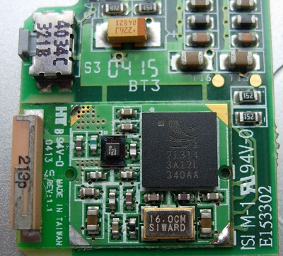
楼主 ;这个伪彩估计能好一些。早上去TB看只剩下15个了,前几天还有好几百个呢,要的话真就得快下手了