|
|
 发表于 2007-10-22 22:13:39
|
显示全部楼层
发表于 2007-10-22 22:13:39
|
显示全部楼层
伟大、光荣、正确的armok先生在所谓的“知识产权”问题上很有一套双重标准啊 。详细的制作过程,有兴趣的看这个吧:
The Arduino Boot-Cloner
What is it? Why?
The boot-cloner is a program compiled and burnt with the Arduino IDE, that copies part of it's flash memory onto another microcontroller. The bootloader can be written to a new microcontroller by the Arduino, instead of burning the bootloader onto new ATmega8's with a separate device.
If you're like me, then you need more than one microcontroller, so you can put the IC into a circuit and leave it there permanently. Unfortunately, burning multiple bootloaders can be a very involved, time consuming process. The cloner will help you get dozens of new ATmega8's ready to use, in seconds. The program gives you access to an implementation of the ISP protocol and declaring and using tables stored in program flash, which don't occupy ram.
Requirements
You need a functioning Arduino that you can already write programs to. If you don't have at least one ATmega8 with a bootloader on it, you'll need to burn it using a separate device, like the parallel port burner.
momentary push button and pull-up resistor 1K ~ 10K Ohms
three leds and current limiting resistors appropriate for the voltage of the device. If you're working from the Arduino, you've got 5V which means 220 Ohm resistors for 20mA. If you build a 2.4V battery powered device, use lower resistors to get 20mA. (Voltage divided by current tells you resistance, so 2.4/.02=12 Ohms, 10 approx)
two ceramic disc capacitors of 10pF (with no polarity) and a 2 to 16MHz crystal oscillator for the target microcontroller. Don't use less than 1MHz; the speed of this crystal determines the maximum rate you can issue commands and send data to the target IC, with ISP. 16MHz was convenient for me, but use whatever you've got on hand.
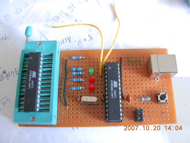
Pictures
More Pictures
Schematic
Notes:
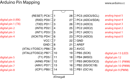
Connect GND on the Arduino to pins 8 and 22 and +5V to pins 7 and 20 on the target microcontroller.
Make sure you have the notch on the target ATmega8 facing up. I can't tell you how many times I've accidentally tried wiring the microcontroller upside-down. The good news is doing that doesn't seem to hurt anything.
Download Project and Schematic
Inner Workings
In-System Programming (ISP) is a protocol developed by Atmel to be used as the primary means of programming their microcontrollers. The three wire serial protocol can be used to write the fuse bits, program memory and eeprom. It's a bit of a language by itself, and varys slightly from one microcontroller to another - mostly by chip architecture differences. (i.e. flash/eeprom size and fuse bit features) While holding the RESET pin of the microcontroller at a low level, the first command issued through ISP is called program enable. After those special 32 bits are sent, the microcontroller begins communicating. There's several commands that can be issued after program enable, which are sent serially at any rate: reading the flash memory, writing the flash memory page-by-page, erasing the flash memory, reading/writing the fuse bits or eeprom, reading device codes and more.
In the Boot-Cloner sketch is an implementation of the ISP protocol for an ATmega8, complete with functions that encapsulate the protocol's commands - making them easier to use. These functions are compatible with many of the other atmel microcontrollers as-is, but haven't been tested yet. The bootloader written to the new ATmega8 is stored in a large array - because default fuse bits of your Arduino prevent reading the boot section. This was a problem I ran into, but the table that had to be added also provides new possibilities.
To sum it all up, this means the Boot-Cloner could write any program to any atmel microcontroller. But, because the target's program must be stored in the source's memory (which limits the maximum size of the program) it's only possible to write small programs like bootloaders.
The ISP protocol is detailed in the Atmel ATmega8 datasheet, towards the end. Additional comments in the sketch's source code describe command parameters and the flash write process.
Step-By-Step Guide
The Arduino will provide power to the entire circuit. Unplug your Arduino before wiring +5V and GND from it, to the target microcontroller. This avoids potential shorts which could damage your hardware. Based on my own experience, it's very difficult to damage the computer or Arduino ~ there's added safety in the design of USB controllers and the ATmega8 is unbelievably tough. Having said that - never feed a different voltage into the 5V or 9V header connectors.
If you should happen to short +5V and GND wires together and your USB port stops providing power - fix the short and then restart your computer. The computer's USB resettable fuse should return to normal. If not, shutdown and power-up your computer. If it still doesn't work, use a different computer or install a new USB adapter card. Some motherboard USB controllers may be more sensitive than others, and provide more or less current than others.
This circuit should draw less than 20+20+20+30mA = 90mA. If either the IC on the Arduino or the target ATmega8 on the breadboard gets warm ~ something's wired incorrectly. Ensure you've got the correct value resistors to the LEDs, suitable pull-up from the button and the right pins are connected on the Arduino.
1) Download and expand the zip archive containing the source code and schematic
2) In the Arduino IDE, open the Boot-Cloner sketch
3) Verify the sketch compiles without error
4) The +5V and GND of your Arduino should be used to power the target ATmega8
I haven't yet had noise problems with this circuit, but avoid using excessively long wires for SCK, MISO, MOSI and avoid working near sources of significant electrical noise.
5) Upon wiring the circuit, according to the schematic, your Arduino should be connected by 10 wires to a breadboard
5V, GND, RESET, SCK, MISO, MOSI, LED1, LED2, LED3, START BTN
6) Ensure you have the chip oriented correctly, and oscillator and power connected to the pins as shown in the schematic
7) Burn the BootCloner sketch to the Arduino and wait for the program to start - you'll see an LED light up according to the program's state
8) At this point, you can push the start button.
The LEDs will change from Idle/Green to Run/Yellow for a moment (less than 4 seconds) and then switch back to Idle/Green.
If the Error/Red LED comes on, it's an indication that your target microcontroller is not responding to the program enable command. This indicates a problem with your wiring. Check to make sure SCK, MISO and MOSI are connected exactly as shown, that you're got the notch/pin1 facing the right direction and that a stable 5V is being provided to your target.
9) Remove the target ATmega8, insert the next.
10) Test the first one you burn, the first time you do this, by putting it in an Arduino and writing the Blinking LED program.
11) If step 10 worked you can repeat steps 8 and 9 until all your ICs are prepared.
Using A Different Bootloader
The bootloader table in the BootCloner sketch holds the raw data which is written to the boot section of the microcontroller. However, a hex file contains memory address and checksums in addition to the raw data. To save space the extra information was discarded and the string hexadecimal numbers were converted to decimal or hexadecimal constants recognizable by the Arduino IDE. (0-255 or 0x00-0xFF)
At the beginning of the BootCloner source code is a reference to a website described as "iHex flash file format information". If you want to understand the format better, that's a great place to start.
The program below, "Hex Data Extractor" can be built into an application that'll extract it for you.
There are also some things in the sketch that need to be changed. How many defined constants need to be modified depends on how different your target microcontroller is than an ATmega8. Ideally you should only have to change the constants, and not the program itself.
Alternate bootloader for an ATmega8:
BOOT_MAX is the size of the bootloader table. Since your bootloader will probably be a different size, you'll need to change this. Arrays in C are zero based, including the bootloader table, so size is the number of bytes minus 1. (0 to 1019 is 1020 bytes)
Alternate bootloader for an ATmega168:
FLASH_MAX should be 16384. (16Kb)
BOOT_PAGE should be 480, if your boot section is 1K. (16384-1024=15360/32=480)
BOOT_MAX is the size of the bootloader table. (byte count minus 1)
Alternate bootloaders for other atmel microcontrollers:
FLASH_MAX, BOOT_PAGE, and BOOT_MAX will most likely need to be changed.
Check the datasheet for your microcontroller to determine how many words (2 bytes) are in a page (PAGE_WORDS).
To my knowledge, there are two different flash write methods. The only one available in the Boot-Cloner is the page method. Your microcontroller might require the other.
Some of the command parameters may need to be altered, such as fuse bits and the largest address size sent to read/write flash and eeprom. This means the functions themselves should be adjusted, as well as the code in the loop() function.
Notes:
I assume that the boot section begins at 7K (BOOT_PAGE) regardless of the size of the bootloader, as long as the fuse bits are set to a 1K boot section.
Technically, you can set BOOT_MAX to 1024 and leave it there. Random junk from the source's flash memory will be written after the bootloader data on the target - but this theoretically doesn't cause problems.
If you want to reduce the bootloaders size below 1K and also free up memory, you'll need to change the corresponding fuse bits to adjust the boot section size and increase the BOOT_PAGE constant.
Hex Data Extractor
/* Data Extractor for Intel Hex Formatted Files
* ------------------
* Created 2007 by jims
* <mailto:jim@federated.com>
*
* Compile this with your preferred C environment, as a standard console app.
* From the console (Command Prompt), launch the app with the hex file pathname.
* The console output will be the extracted hex data.
*
*/
#include <stdio.h>
#include <string.h>
main()
{
char buf[4096];
int n = 0;
while( fgets(buf, sizeof(buf)-1, stdin)) {
int len = strlen(buf);
char *b;
if ( len < 9) continue;
buf[len-4] = 0;
for ( b = buf+9; *b != 0; b += 2) {
printf("0x%c%c, ", b[0], b[1]);
n++;
}
printf("\n");
}
printf("/* %d bytes */\n", n);
}
Boot-Cloner Source Code
/* ARDUINO BOOT-CLONER
* -------------------
*
* Comments
*
* The ATmega8 fuse bytes and bootloader are copied
* from the chip on the Arduino, to a new blank ATmega8.
*
* / See app note DOC0943.pdf "AVR910: In-System Programming"
* / See app note DOC2486.pdf "ATmega8 Documentation" - The chapter on Memory Programming, p.237/240
* / iHex flash file format information "http://www.scienceprog.com/shelling-the-intel-8-bit-hex-file-format/"
* / PROGMEM and pgmspace.h usage information:
* "http://www.scienceprog.com/simple-routine-how-to-store-data-in-microcontroller-flash-and-read-from-it-using-winavr/"
*
* Notes:
* Sometimes the program wont detect errors, i.e. if the target ic isn't inserted.
* Contrary to what I originally thought, the bootloader resides at the end of flash memory.
*
* The program was too big, so some of the extra functions are commented out to save memory.
*
* This program hasn't been optimized for speed, but it's still pretty quick. Some of the delays are unnecessary.
*
* Your bootloader flash probably can't be read; the default lock bits prevent that. (0xCF ~ bit 6)
* This boot-cloner writes different lock bits to the new ATmega8; so the boot flash section *could* be read
* when run from the new chip. (0xEF)
* With the bootloader flash unlocked, you could remove the bootloader[] table and save a bunch of memory.
*
* 2007 by Amplificar
* <mailto:amplificar@gmail.com>
*
*/
// need this header for PROGMEM and the command pgm_read_byte()
// which reads bytes from flash program memory.
// you can view the header's contents, which are in arduino->tools->avr->avr->include->avr->pgmspace.h
#include <avr/pgmspace.h>
// CONSTANT DECLARATION
// target microcontroller constants
#define FLASH_MAX 8192
// the flash size
#define PAGE_WORDS 32
// the number of words per page
#define BOOT_PAGE 112
// the starting page number, where the bootloader lurks (8192/2/32=128, 1024/2/32=16, 128-16=112)
// the bootloader data; distributed with arduino ide 0005
// this is the extracted data from the ihex file
// PROGMEM forces this data to be kept in the flash - and not get loaded into ram (that'd be bad)
// this table has to be read back using "byte=pgm_read_byte(&bootloader[index]);"
#define BOOT_MAX 1019
const unsigned char bootloader[] PROGMEM= {
0x12,0xC0,0x2B,0xC0,0x2A,0xC0,0x29,0xC0,0x28,0xC0,0x27,0xC0,0x26,0xC0,0x25,0xC0,
0x24,0xC0,0x23,0xC0,0x22,0xC0,0x21,0xC0,0x20,0xC0,0x1F,0xC0,0x1E,0xC0,0x1D,0xC0,
0x1C,0xC0,0x1B,0xC0,0x1A,0xC0,0x11,0x24,0x1F,0xBE,0xCF,0xE5,0xD4,0xE0,0xDE,0xBF,
0xCD,0xBF,0x10,0xE0,0xA0,0xE6,0xB0,0xE0,0xE6,0xEF,0xFF,0xE1,0x02,0xC0,0x05,0x90,
0x0D,0x92,0xA2,0x36,0xB1,0x07,0xD9,0xF7,0x11,0xE0,0xA2,0xE6,0xB0,0xE0,0x01,0xC0,
0x1D,0x92,0xAA,0x36,0xB1,0x07,0xE1,0xF7,0x4B,0xC0,0xD2,0xCF,0xEF,0x92,0xFF,0x92,
0x0F,0x93,0x1F,0x93,0xEE,0x24,0xFF,0x24,0x87,0x01,0x5F,0x99,0x15,0xC0,0x08,0x94,
0xE1,0x1C,0xF1,0x1C,0x01,0x1D,0x11,0x1D,0x81,0xE0,0xE8,0x16,0x82,0xE1,0xF8,0x06,
0x8A,0xE7,0x08,0x07,0x80,0xE0,0x18,0x07,0x28,0xF0,0xE0,0x91,0x62,0x00,0xF0,0x91,
0x63,0x00,0x09,0x95,0x5F,0x9B,0xEB,0xCF,0x8C,0xB1,0x99,0x27,0x87,0xFD,0x90,0x95,
0x1F,0x91,0x0F,0x91,0xFF,0x90,0xEF,0x90,0x08,0x95,0x5D,0x9B,0xFE,0xCF,0x8C,0xB9,
0x08,0x95,0xD4,0xDF,0x80,0x32,0x21,0xF4,0x84,0xE1,0xF7,0xDF,0x80,0xE1,0xF5,0xDF,
0x08,0x95,0x08,0x95,0xCF,0x93,0xC8,0x2F,0xC9,0xDF,0x80,0x32,0x31,0xF4,0x84,0xE1,
0xEC,0xDF,0x8C,0x2F,0xEA,0xDF,0x80,0xE1,0xE8,0xDF,0xCF,0x91,0x08,0x95,0xCF,0x93,
0x88,0x23,0x21,0xF0,0xC8,0x2F,0xBA,0xDF,0xC1,0x50,0xE9,0xF7,0xCF,0x91,0x08,0x95,
0xCF,0xE5,0xD4,0xE0,0xDE,0xBF,0xCD,0xBF,0x00,0x00,0x10,0xBC,0x83,0xE3,0x89,0xB9,
0x88,0xE1,0x8A,0xB9,0x86,0xE8,0x80,0xBD,0xBD,0x9A,0x10,0x92,0x68,0x01,0x30,0xE2,
0x2F,0xE0,0x88,0xB3,0x83,0x27,0x88,0xBB,0x80,0xE0,0x90,0xE0,0x01,0x97,0xF1,0xF7,
0x21,0x50,0x27,0xFF,0xF6,0xCF,0x20,0xE1,0x20,0x93,0x68,0x01,0x97,0xDF,0x80,0x33,
0x09,0xF4,0x44,0xC0,0x81,0x33,0xA1,0xF4,0x91,0xDF,0xC8,0x2F,0x80,0x32,0xB1,0xF7,
0x84,0xE1,0xB3,0xDF,0x81,0xE4,0xB1,0xDF,0x86,0xE5,0xAF,0xDF,0x82,0xE5,0xAD,0xDF,
0x8C,0x2F,0xAB,0xDF,0x89,0xE4,0xA9,0xDF,0x83,0xE5,0xA7,0xDF,0x80,0xE5,0x2E,0xC1,
0x80,0x34,0x29,0xF4,0x7B,0xDF,0x86,0x38,0x48,0xF1,0x78,0xDF,0x27,0xC0,0x81,0x34,
0x71,0xF4,0x74,0xDF,0x80,0x38,0x11,0xF4,0x82,0xE0,0x28,0xC1,0x81,0x38,0x11,0xF4,
0x81,0xE0,0x24,0xC1,0x82,0x38,0x09,0xF0,0x20,0xC1,0x82,0xE1,0x1F,0xC1,0x82,0x34,
0x11,0xF4,0x84,0xE1,0x03,0xC0,0x85,0x34,0x19,0xF4,0x85,0xE0,0xA0,0xDF,0x0E,0xC0,
0x80,0x35,0x61,0xF0,0x81,0x35,0x51,0xF0,0x82,0x35,0x41,0xF0,0x85,0x35,0x41,0xF4,
0x55,0xDF,0x80,0x93,0x64,0x00,0x52,0xDF,0x80,0x93,0x65,0x00,0x7A,0xDF,0xB6,0xCF,
0x86,0x35,0x19,0xF4,0x84,0xE0,0x8B,0xDF,0x00,0xC1,0x84,0x36,0x09,0xF0,0x9D,0xC0,
0x45,0xDF,0x80,0x93,0x67,0x01,0x42,0xDF,0x80,0x93,0x66,0x01,0x80,0x91,0x69,0x01,
0x8E,0x7F,0x80,0x93,0x69,0x01,0x3A,0xDF,0x85,0x34,0x29,0xF4,0x80,0x91,0x69,0x01,
0x81,0x60,0x80,0x93,0x69,0x01,0xC0,0xE0,0xD0,0xE0,0x80,0x91,0x66,0x01,0x90,0x91,
0x67,0x01,0xC8,0x17,0xD9,0x07,0x70,0xF4,0x06,0xE6,0x10,0xE0,0x27,0xDF,0xF8,0x01,
0x81,0x93,0x8F,0x01,0x21,0x96,0x80,0x91,0x66,0x01,0x90,0x91,0x67,0x01,0xC8,0x17,
0xD9,0x07,0xA0,0xF3,0x1B,0xDF,0x80,0x32,0x09,0xF0,0x80,0xCF,0x80,0x91,0x69,0x01,
0x80,0xFF,0x26,0xC0,0xC0,0xE0,0xD0,0xE0,0x80,0x91,0x66,0x01,0x90,0x91,0x67,0x01,
0xC8,0x17,0xD9,0x07,0x08,0xF0,0x5F,0xC0,0x06,0xE6,0x10,0xE0,0xF8,0x01,0x61,0x91,
0x8F,0x01,0x80,0x91,0x64,0x00,0x90,0x91,0x65,0x00,0xC2,0xD0,0x80,0x91,0x64,0x00,
0x90,0x91,0x65,0x00,0x01,0x96,0x90,0x93,0x65,0x00,0x80,0x93,0x64,0x00,0x21,0x96,
0x80,0x91,0x66,0x01,0x90,0x91,0x67,0x01,0xC8,0x17,0xD9,0x07,0x38,0xF3,0x43,0xC0,
0xF8,0x94,0xE1,0x99,0xFE,0xCF,0x11,0x27,0xE0,0x91,0x64,0x00,0xF0,0x91,0x65,0x00,
0xEE,0x0F,0xFF,0x1F,0xC6,0xE6,0xD0,0xE0,0x80,0x91,0x66,0x01,0x90,0x91,0x67,0x01,
0x80,0xFF,0x01,0xC0,0x01,0x96,0x10,0x30,0x51,0xF4,0x22,0xD0,0x03,0xE0,0x00,0x93,
0x57,0x00,0xE8,0x95,0x1D,0xD0,0x01,0xE1,0x00,0x93,0x57,0x00,0xE8,0x95,0x09,0x90,
0x19,0x90,0x16,0xD0,0x01,0xE0,0x00,0x93,0x57,0x00,0xE8,0x95,0x13,0x95,0x10,0x32,
0x58,0xF0,0x11,0x27,0x0D,0xD0,0x05,0xE0,0x00,0x93,0x57,0x00,0xE8,0x95,0x08,0xD0,
0x01,0xE1,0x00,0x93,0x57,0x00,0xE8,0x95,0x32,0x96,0x02,0x97,0x39,0xF0,0xDB,0xCF,
0x00,0x91,0x57,0x00,0x01,0x70,0x01,0x30,0xD9,0xF3,0x08,0x95,0x10,0x30,0x11,0xF0,
0x02,0x96,0xE7,0xCF,0x11,0x24,0x84,0xE1,0x59,0xC0,0x84,0x37,0x09,0xF0,0x49,0xC0,
0xA5,0xDE,0x80,0x93,0x67,0x01,0xA2,0xDE,0x80,0x93,0x66,0x01,0x9F,0xDE,0x90,0x91,
0x69,0x01,0x85,0x34,0x21,0xF4,0x91,0x60,0x90,0x93,0x69,0x01,0x0D,0xC0,0x9E,0x7F,
0x90,0x93,0x69,0x01,0x80,0x91,0x64,0x00,0x90,0x91,0x65,0x00,0x88,0x0F,0x99,0x1F,
0x90,0x93,0x65,0x00,0x80,0x93,0x64,0x00,0x89,0xDE,0x80,0x32,0x09,0xF0,0xEE,0xCE,
0x84,0xE1,0xAB,0xDE,0xC0,0xE0,0xD0,0xE0,0x80,0x91,0x66,0x01,0x90,0x91,0x67,0x01,
0xC8,0x17,0xD9,0x07,0x60,0xF5,0x80,0x91,0x69,0x01,0x80,0xFF,0x06,0xC0,0x80,0x91,
0x64,0x00,0x90,0x91,0x65,0x00,0x2C,0xD0,0x08,0xC0,0x86,0x95,0x80,0xFD,0x06,0xC0,
0xE0,0x91,0x64,0x00,0xF0,0x91,0x65,0x00,0x84,0x91,0x8F,0xDE,0x80,0x91,0x64,0x00,
0x90,0x91,0x65,0x00,0x01,0x96,0x90,0x93,0x65,0x00,0x80,0x93,0x64,0x00,0x21,0x96,
0xDB,0xCF,0x85,0x37,0x79,0xF4,0x5A,0xDE,0x80,0x32,0x09,0xF0,0xBF,0xCE,0x84,0xE1,
0x7C,0xDE,0x8E,0xE1,0x7A,0xDE,0x83,0xE9,0x78,0xDE,0x87,0xE0,0x76,0xDE,0x80,0xE1,
0x74,0xDE,0xB4,0xCE,0x86,0x37,0x09,0xF0,0xB1,0xCE,0x80,0xE0,0x7B,0xDE,0xAE,0xCE,
0xE1,0x99,0xFE,0xCF,0x9F,0xBB,0x8E,0xBB,0xE0,0x9A,0x99,0x27,0x8D,0xB3,0x08,0x95,
0xE1,0x99,0xFE,0xCF,0x9F,0xBB,0x8E,0xBB,0x6D,0xBB,0x0F,0xB6,0xF8,0x94,0xE2,0x9A,
0xE1,0x9A,0x0F,0xBE,0x08,0x95,
0x80,0x00,
0x00,0x00,0x1C,0x00
};
// PINS
#define SCK 13
// serial clock to target avr
#define MISO 12
// input from target avr
#define MOSI 11
// output to target avr
#define RESET 10
// reset pin of the target avr
#define START_BTN 9
// active low - starts burning the bootloader to the new chip
#define IDLE_LED 8
#define RUN_LED 7
#define ERR_LED 6
// on the target avr, wire these other pins:
// GND: pins 22 (GND), 8 (GND)
// +VCC: pin 7 (VCC)
// XTAL1 & XTAL2
#define CKEDGE LOW
// SCK transmits the bit from MOSI on the rising edge of the clock pulse
// CKEDGE should be LOW, which means SCK pulses "...LOW->HIGH->LOW..."
// ISP Command Words (use the functions defined further below)
#define PE 0xAC53
#define ER 0xAC80
#define RD_PL 0x2000
#define RD_PH 0x2800
#define LD_PL 0x4000
#define LD_PH 0x4800
#define WR_P 0x4C00
#define RD_E 0xA000
#define WR_E 0xC000
#define RD_L 0x5800
#define WR_L 0xACE0
#define RD_S 0x3000
#define WR_F 0xACA0
#define WR_FH 0xACA8
#define RD_F 0x5000
#define RD_FH 0x5808
#define RD_C 0x3800
// Arduino lock bits (default 0xCF ~ prevented reading the boot sector with LPM)
#define LockBits 0xEF
// 11101111 = SPM is not allowed to write to the boot loader section (prevents bootloader corruption)
// Your mega8 running this program probably has bit 6 is programmed. That lock bit makes the bootloader unreadable... (doh!)
// When you use this program to burn new bootloaders, those chips WILL be able to use LPM in the boot flash section.
// You could reduce this program's size by 1K, if LPM can read the boot flash. (there'd be no need for the bootloader table above)
// Arduino fuse bits
#define FuseLow 0xDF
// default 11011111 = 0xDF, bits 1-4 (rightmost) are CKSEL clock select, bits 5-6 are SUT1 & SUT0 start up time delay
// bits 7-8 are BOD brown out detect, which is disabled
#define FuseHigh 0xCA
// default 11001010 = 0xCA
// bit 1 select reset vector (on)
// bits 2-3 boot size (1K)
// bit 4 EESAVE eeprom preserved through chip erase (off)
// bit 5 CKOPT clock options (on)
// bit 6 SPIEN SPI enabled (on)
// bit 7 WDT watchdog timer (off)
// bit 8 RSTDISBL reset disable (off)
// MACRO DECLARATION
#define PULSE_SCK(level) { digitalWrite((SCK),(level)); digitalWrite((SCK),!(level)); }
// slow pulse, max 60KHz
#define GetWordHigh(a) ( ((a) & 0xFF00) >> 8 )
#define GetWordLow(a) ( ((a) & 0x00FF) )
// these macros are used by the function declarations below
// FUNCTION DECLARATION
// sends 4 bytes out with SCK, MOSI (output) and gets the return value of the last byte from MISO (input)
unsigned char Send_ISP(unsigned char v0, unsigned char v1, unsigned char v2, unsigned char v3);
#define CMD_Program_Enable() (Send_ISP(GetWordHigh(PE),GetWordLow(PE),0x22,0x22))
// Programming Enable: enable serial programming after reset goes low
#define CMD_Erase_Flash() (Send_ISP(GetWordHigh(ER),GetWordLow(ER),0x22,0x22))
// Chip Erase: chip erase eeprom and flash
#define CMD_Read_Flash_Low(addr) (Send_ISP(GetWordHigh(RD_PL), (GetWordLow(RD_PL) | (((addr) & 0xF00) >> 8)), ((addr) & 0xFF), 0))
// Read Program Memory - Low Byte: reads and returns low data from 12 bit word address (divide byte address by 2 for word address)
#define CMD_Read_Flash_High(addr) (Send_ISP(GetWordHigh(RD_PH), (GetWordLow(RD_PH) | (((addr) & 0xF00) >> 8)), ((addr) & 0xFF), 0))
// Read Program Memory - High Byte: reads and returns high data from 12 bit word address
#define CMD_Load_Page_Low(addr,data) (Send_ISP(GetWordHigh(LD_PL),GetWordLow(LD_PL), (addr), (data)))
// Load Program Memory Page - Low Byte: loads a low byte to the selected memory page, at word address "page" (page is 4 bits)
// data low byte must be loaded before data high byte; the flash data is entered by pages, then that whole page is written
// pages are 32 words (64 bytes)
#define CMD_Load_Page_High(addr,data) (Send_ISP(GetWordHigh(LD_PH),GetWordLow(LD_PH), (addr), (data)))
// Load Program Memory Page - High Byte: loads a high byte to program memory page at word address "page" (page is 4 bits)
// data low byte must be loaded before data high byte; the flash data is entered by pages, then that whole page is written
// pages are 32 words (64 bytes)
//#define CMD_Write_Page(addr)
//(Send_ISP(GetWordHigh(WR_P),(GetWordLow(WR_P) | (((addr) & 0xF0) >> 4)), (((addr) & 0x0F) << 4), 0))
// this is how it's supposed to be done, according to the documentation, but it doesn't work as it's supposed to.
// the code below works correctly, by multiplying the address by 2?... very weird
#define CMD_Write_Page(addr) (Send_ISP(GetWordHigh(WR_P),(((addr)*2) & 0xF0) >> 4, ((addr)*2) << 4, 0))
// Write Program Memory Page: write the current page into flash memory at the 8 bit page address "addr"
// your program must wait or poll after performing this command; otherwise the page writing will be halted
// each page is 32 words (64 bytes) - 8K bytes flash, or 4096 words, is 128 pages (0 thru 127)
// 1K flash (bootloader) is 1024 bytes, 512 words - which is 16 pages
// the bootloader begins at 7K (7168 /2=3584) which is page address 112
#define CMD_Read_EEPROM(addrH,addrL) (Send_ISP(GetWordHigh(RD_E),(GetWordLow(RD_E) | ((addrH) & 0x01)), (addrL), 0))
// Read EEPROM Memory: reads and returns data from the 9 bit address to the EEPROM (addrH is 1 bit, addrL is 8 bit)
#define CMD_Write_EEPROM(addrH,addrL,data) (Send_ISP(GetWordHigh(WR_E),(GetWordLow(WR_E) | ((addrH) & 0x01)), (addrL), (data)))
// Write EEPROM Memory: writes data from the 9 bit address to the EEPROM (addrH is 1 bit, addrL is 8 bit)
#define CMD_Read_Lock() (Send_ISP(GetWordHigh(RD_L),GetWordLow(RD_L), 0, 0))
// Read Lock Bits: read the 6 lock bits; "0" is programmed, 1 is unprogrammed
#define CMD_Write_Lock(data) (Send_ISP(GetWordHigh(WR_L),GetWordLow(WR_L), 0, (0xC0 | ((data) & 0x3F)) ))
// Write Lock Bits: write the 6 lock bits; "0" is programmed, 1 is unprogrammed
#define CMD_Read_Signature(addr) (Send_ISP(GetWordHigh(RD_S),GetWordLow(RD_S), ((addr) & 0x03) , 0))
// Read Signature Byte: reads and returns the signature byte from the 2 bit address
#define CMD_Write_Fuse_Low(data) (Send_ISP(GetWordHigh(WR_F),GetWordLow(WR_F), 0, (data) ))
// Write Fuse Bits - Low: writes the low fuse bits (8 bits)
#define CMD_Write_Fuse_High(data) (Send_ISP(GetWordHigh(WR_FH),GetWordLow(WR_FH), 0, (data) ))
// Write Fuse Bits - High: writes the high fuse bits (8 bits)
#define CMD_Read_Fuse_Low() (Send_ISP(GetWordHigh(RD_F),GetWordLow(RD_F), 0, 0 ))
// Read Fuse Bits - Low: reads and returns the low fuse bits (8 bits)
#define CMD_Read_Fuse_High() (Send_ISP(GetWordHigh(RD_FH),GetWordLow(RD_FH), 0, 0 ))
// Read Fuse Bits - High: reads and returns the high fuse bits (8 bits)
#define CMD_Read_Calibration() (Send_ISP(GetWordHigh(RD_C),GetWordLow(RD_C), 0, 0 ))
// Read Calibration Byte: reads and returns the calibration byte (8 bits)
void Reset_Target(); // resets the target avr
void Read_Signature(); // prints the 16 signature bytes (device codes)
void Read_Flash(); // prints the target flash memory
void Read_Fuse(); // prints the lock and fuse bits (no leading zeros)
void Show_Bootloader(); // prints the contents of the bootloader table (for debugging)
void Write_Test(); // testing/debugging; writes the address number to each address
void setup(void) {
pinMode(SCK,OUTPUT);
pinMode(MISO,INPUT);
pinMode(MOSI,OUTPUT);
pinMode(RESET,OUTPUT);
// user interface
pinMode(START_BTN,INPUT);
pinMode(IDLE_LED,OUTPUT);
pinMode(RUN_LED,OUTPUT);
pinMode(ERR_LED,OUTPUT);
Serial.begin(19200);
}
void loop(void) {
unsigned int result = 0; // used for debugging & showing errors
digitalWrite(ERR_LED,LOW);
digitalWrite(RUN_LED,LOW);
digitalWrite(IDLE_LED,HIGH); // indicate idle/waiting
do {} while (digitalRead(START_BTN));
digitalWrite(ERR_LED,LOW);
digitalWrite(RUN_LED,HIGH);
digitalWrite(IDLE_LED,LOW); // indicate running
Serial.println("Starting...");
Reset_Target();
if ( result=CMD_Program_Enable() != 0x22 ) {
Serial.print("Program Enable "); // an error occurred; expected 0x22
goto SHOW_ERROR;
// error detection routine isn't foolproof.
}
Serial.println("Setting Fuses");
CMD_Write_Fuse_Low(FuseLow);
delay(20);
CMD_Write_Fuse_High(FuseHigh);
delay(20);
CMD_Write_Lock(LockBits);
delay(20);
Reset_Target();
if ( result=CMD_Program_Enable() != 0x22 ) {
Serial.print("Program Enable "); // an error occurred; expected 0x22
goto SHOW_ERROR;
// error detection routine isn't foolproof.
}
Serial.println("Erasing Flash");
CMD_Erase_Flash();
delay(20);
Reset_Target();
if ( result=CMD_Program_Enable() != 0x22 ) {
Serial.print("Program Enable "); // an error occurred; expected 0x22
goto SHOW_ERROR;
}
for ( unsigned char page = BOOT_PAGE ; page <= BOOT_PAGE+BOOT_MAX/2/PAGE_WORDS ; page++ ) {
for ( unsigned char index = 0 ; index < PAGE_WORDS && (index+(page-BOOT_PAGE)*PAGE_WORDS)*2 < BOOT_MAX ; index++ ) {
CMD_Load_Page_Low(index,pgm_read_byte(&bootloader[((page-BOOT_PAGE)*PAGE_WORDS+index)*2]));
CMD_Load_Page_High(index,pgm_read_byte(&bootloader[((page-BOOT_PAGE)*PAGE_WORDS+index)*2+1]));
//Serial.println(((page-BOOT_PAGE)*PAGE_WORDS+index)*2,DEC);
}
Serial.print("Writing page ");
Serial.println(page,DEC);
CMD_Write_Page(page);
delay(20);
}
// in the condition of the outermost, first loop, BOOT_MAX is number of bytes in the bootloader table
// that's divided by 2 to get words (a word is 2 bytes) and divided by PAGE_WORDS (32) to determine
// the total number of pages to be written
// in the condition of the innermost loop, the stuff following && prevents the last page from being completely written
// when the bootloader isn't an even multiple of 32. (it'd write random junk from this chips flash memory)
// the condition checks to see if the index, plus the page, exceeds the number of bytes in the bootloader table.
// the CMD_Load_Page_Low(...) does some math to convert index & page into an index for the bootloader table
// the Low byte must be written before the High byte, when programming
// once the page buffer is filled, the CMD_Write_Page() is issued, which commits the page to flash memory.
//Read_Flash();
// prints the contents of the target microcontroller's flash (slow)
return;
SHOW_ERROR:
Serial.print("ERROR (result ");
Serial.print(result,BIN);
Serial.println(")");
digitalWrite(ERR_LED,HIGH);
digitalWrite(RUN_LED,LOW);
digitalWrite(IDLE_LED,LOW); // indicate error
do {} while (digitalRead(START_BTN));
return;
}
// send 4 bytes to target microcontroller, returns the fourth MISO byte
unsigned char Send_ISP(unsigned char v0, unsigned char v1, unsigned char v2, unsigned char v3) {
// MO output
// MI input
unsigned char result = 0;
// first byte
for ( int i = 0x80 ; i>0 ; i /= 2 ) {
digitalWrite(MOSI,(v0 & i));
PULSE_SCK(CKEDGE);
//result = ((result << 1) | digitalRead(MISO)); // shift contents of result left one bit, set LSB with MISO value
}
for ( int i = 0x80 ; i>0 ; i /= 2 ) { // second byte - MISO echos first byte
digitalWrite(MOSI,(v1 & i));
PULSE_SCK(CKEDGE);
result = ((result << 1) | digitalRead(MISO));
}
if (result != v0 ) { // handle error
}
for ( int i = 0x80 ; i>0 ; i /= 2 ) { // third byte - MISO echos second byte
digitalWrite(MOSI,(v2 & i));
PULSE_SCK(CKEDGE);
result = ((result << 1) | digitalRead(MISO));
}
if (result != v1 ) { // handle error
}
for ( int i = 0x80 ; i>0 ; i /= 2 ) { // fourth byte - MISO returns some value (depends on command)
digitalWrite(MOSI,(v3 & i));
PULSE_SCK(CKEDGE);
result = ((result << 1) | digitalRead(MISO));
}
return result;
}
void Reset_Target() {
digitalWrite(RESET,HIGH);
digitalWrite(SCK,LOW); // has to be set LOW at startup, or PE fails
delay(30);
digitalWrite(RESET,LOW);
delay(30); // minimum delay here is 20ms for the ATmega8
}
// prints the 16 signature bytes (device codes)
/*void Read_Signature() {
Serial.println("SIGNATURES");
for ( unsigned char x = 0 ; x<16 ; x++ ) {
Serial.print(CMD_Read_Signature(x),HEX);
Serial.print(",");
}
Serial.println("");
Serial.println("END SIGNATURES");
}*/
// prints the flash memory
void Read_Flash() {
unsigned int value = 0;
Serial.println("READING FLASH");
for ( unsigned int index = 0 ; index<(FLASH_MAX/2) ; index++ ) {
if ( (index % PAGE_WORDS) == 0) {
Serial.println("");
Serial.print("Page ");
Serial.print(index/PAGE_WORDS,DEC);
Serial.print(" = ");
if ( index/PAGE_WORDS < 100)
Serial.print(" ");
} else if ( (index % (PAGE_WORDS/2)) == 0) {
Serial.println("");
Serial.print(" ");
}
Serial.print(CMD_Read_Flash_Low(index),HEX);
Serial.print(" ");
Serial.print(CMD_Read_Flash_High(index),HEX);
Serial.print(" ");
}
Serial.println("");
Serial.println("END FLASH");
}
// prints the lock and fuse bits (no leading zeros)
void Read_Fuse() {
Serial.print("Lock Bits: ");
Serial.println(CMD_Read_Lock(),BIN);
Serial.print("Fuse Low: ");
Serial.println(CMD_Read_Fuse_Low(),BIN);
Serial.print("Fuse High: ");
Serial.println(CMD_Read_Fuse_High(),BIN);
}
// prints the contents of the bootloader table
/*void Show_Bootloader() {
Serial.println("SHOWING BOOTLOADER");
for ( unsigned int index = 0 ; (index <= BOOT_MAX) ; index++ ) {
Serial.print(pgm_read_byte(&bootloader[index]),HEX);
Serial.print(",");
}
Serial.println("");
Serial.println("END BOOTLOADER");
}*/
/*void Write_Test() {
for ( unsigned char page = 0 ; page<128 ; page++ ) {
Serial.print("Writing page ");
Serial.println(page,DEC);
for ( unsigned char index = 0 ; index<32 ; index++ ) {
CMD_Load_Page_Low(index,(page*32)+index);
CMD_Load_Page_High(index,((page*32)+index) >> 8);
}
CMD_Write_Page(page);
delay(20);
}
}*/
Projects Built with Arduino
Manuals
Arduino Tutorials
Official tutorial page
Information on the Arduino Mini
Bluetooth tutorial
Xbee (Zigbee) tutorial
DIY Arduino Shield
Serial LCD tutorial
Learning Electronics
Learning Programming
Asuro Robot and Arduino
Let the Arduino Sleep
Burning Bootloaders
CourseWare
SFU-SIAT Arduino Course Site
Stand alone 3.3V 8 MHz
Programming the Bluetooth WT11
Retrofitting Diecimila AutoReset
Bare Bones "Diecimila" Upgrade
Run Arduino on...
Linux
Ubuntu Linux
Debian Linux
Gentoo Linux
Slackware Linux
FreeBSD
Fedora Linux
The command line
Interface Arduino with...
Instant Reality (X3D)
Flash
Processing
PD (Pure Data)
Max/MSP/Jitter
VVVV
Director
Ruby
C
Linux TTY
Windows HyperTerminal
SuperCollider
Second Life
Firmata
SimpleMessageSystem Library
Python
other
Connect Hardware...
Code for the 74XX151
analog De/Mutliplexer 4051
Code for LCD displays
Serial LCD tutorial
Sparkfun SerLCD
DMX512
LED_Matrix
LED Sign
Rotary encoders
PS2 mouse interface
Effects processor controller
XBee Shield
ArduinoBT to Mobile Phone
Telephone style keypad
Computer brushless fan
SID-emulator
VMUSIC
Arduino Synth Page
Usb Memory Stick
Code Library
Native Capacitive Sensors
EEPROM and Flash tricks
Simple Message System
Metro Library
Interrupt example
Bit Math Tutorial
Windows command-line build
Make Arduino 0007 sketches smaller
Copy Bootloaders - BootCloner
Bootloader Development
Python 2B Protocol
Sketch Library
dataflash memory library
Resources
online electronic suppliers
local shops
datasheets
Arduino-like boards
Workshops
Languages?
Español - Spanish
Français
Projets
Italiano
People/Groups & Sites
--------------------------------------------------------------------------------
PARTICIPATE
request contributor access
suggestions
formatting suggestions
PmWiki
WikiSandBox training
Basic Editing
Cookbook (addons)
Documentation Index)
--------------------------------------------------------------------------------
login logout edit SideBar admin
Login |
|


 楼主
楼主